

Design of shear wall:
The vertical structural element of a reinforced concrete framed structure which is provided to resist in-plane lateral loads is known as shear wall. The design of shear wall is necessary to resist the in-plane shear and in-plane flexural moment caused by lateral loads through the vertical cantilever Action. Here we discuss about the design of shear wall located around the lift.
Design a shear wall of a building which is located in three side if the lift as shown. Grade of concrete = M25 and grade of steel = Fe 500
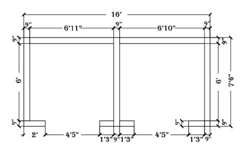
Total length of the wall = 192 + 90*3+15*4+9*2= 549 in. = 13.9446 m.
Floor height = 3.2004 m.
Wall thickness = 9 in. = 0.2286 m.
The stepwise design of shear wall procedure is as follows:
Check for slenderness ratio:
Eff. Height of wall, he = 0.75H = 0.75*3.2004 = 2.4003m
Slenderness ratio, he/t = 2.4003/0.2286 = 10.50 < 30 OK.
Min. eccentricity, E min = e = 0.05t (Clause 32.2.2, IS 456:2000)
= 0.05*0.2286=0.01143m = 11.43mm
Additional eccentricity (ea) = he2/2500t
= 2.40032/ (2500*0.2286) = 0.010813m = 10.813 mm
Calculation of load:
- Ground floor:
Length = 13.9446 m
Height =2.798/2+3.2004/2 = 2.9992m.
Load = 25*13.9446*2.9992*0.2286 = 239.01 KN
2. Typical Floor:
Length = 13.9446 m
Height = 3.2004/2+3.2004/2 = 3.2004 m
Load = 25*13.9446*3.2004*0.2286 = 255.05 KN
3. Second last Floor:
Length = 13.9446 m.
Height = 3.2004/2+2.8956/2 = 3.048m.
Load = 25 * 13.9446 * 3.048 * 0.2286 = 242.90 KN
4. Top Floor:
Length = 13.9446 m
Height = 2.8956/2 = 1.4478
Load = 25*13.9446*1.4478*0.2286 = 115.3808 KN
Roof load:
Plan area = 192” * 90” = 4.8768 m * 2.286 m = 11.1483 m2.
Slab thickness = 150 mm = 0.15 m
Slab load = 11.1483*0.15*25 = 41.80 KN.
Total Top Floor Load = 115.3808 + 41.80 =157.18 KN
Total load = 239.01+9*255.05+242.90+157.18 = 2934.54 KN
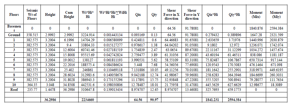
Calculation of base shear:
Total seismic weight of lift (W) = 2934.54 KN
Height, h = 37.698m
Base shear, Vb = Ah*W (Clause 7.5.3, IS 1893 (Part 1) : 2002)
Where,
Ah = design horizontal acceleration spectrum
W = seismic weight as per (Clause 7.4.2, IS 1893 (Part 1) : 2002)
Now, Ah = 𝑍𝐼𝑆a/2𝑅𝑔 (Clause 6.4.2, IS 1893 (Part 1) : 2002)
Where,
Z = zone factor = 0.36 for Seismic Zone V (Table 2, IS 1893 (Part 1) : 2002)
I = importance factor = 1 (Table 6, IS 1893 (Part 1) : 2002)
R = response reduction factor=5 (Table 7, IS 1893 (Part 1) : 2002)
Sa/g = average response acceleration coefficient
Width of Shear wall:
DY = 4.8768 m.
DX = 2.2860 m
Time Period (TA) = 0.09ℎ√𝑑 (Clause 7.6.2, IS 1893 (Part 1) : 2002)
TAy = 0.09∗37.698√4.8768
=1.53 sec.
TAx = 0.09∗37.698√2.2860
= 2.24 sec.
For soil type of type II
For TAy =1.53 sec.
(Sa/g)Y = 1.361.53 = 0.88
Ahy=0.36*1*0.88 / (2*5)
=0.031
Again, For TAx = 2.24 sec.
(Sa/g)X = 1.362.24 =0.607
Ahx =0.36*1*0.607 / (2*5)
=0.022
Now,
Base shear (Vby) = Ahy*W = 0.033*2934.54 = 90.97 KN
Base shear (Vbx) = Ahx*W = 0.022*2934.54 = 64.56 KN
The deign axial strength of a wall per unit length,
Puw = 0.3(t-1.2e-2ea) fck (Clause 32.2.5, IS 456 : 2000)
Where, t= thickness of the wall
e = eccentricity
ea = additional eccentricity due to slenderness effect taken as Hwe2/2500t.
Puw = 0.3(228.60-1.2*11.43-2*10.813)*25 = 1460.41 N/mm.
Calculation for main vertical reinforcement:
Assume clear cover 15 mm. and 12mm dia. bars.
When lateral load is acting along X – direction:
Mu/3 = 1.5∗1840.876/3 = 920.438 KNm
Vu/3= 1.5∗64.56/3 = 32.28 KN
Pu/3= 1.5∗2934.54 /3 = 1467.27 KN
d’/D = (15+6)/4876.80 = 0.0043. (Adopt 0.05)
Mu/fckbd2 = 920.438*106/ (25*228.60*22862) = 0.0308
Pu/fckbd = 1467.27*1000/ (25*2286*228.60) = 0.1123
Using chart 35 SP 16:
p/fck = 0.00
Check for minimum reinforcement:
Ast, min = 0.0025 * bD = 0.0025*228.60*2286 = 1306.45 mm2.
Ab = 𝜋 * 122/4 = 113.0973 mm2
Spacing of bars = 2286 * 113.0973 / 1306.45 = 197.89 mm.
Check for spacing of bar
Spacing ≤ 3t or 450 mm whichever is less
=3*228.6 or 450mm
=685.8 or 450 OK
To take account of opposite phenomena, Provide 12 mm dia bar @ 180mm c/c on both sides.
When lateral force is acting along Y-direction
Mu= 1.5 * 2761.59 = 3891.576 KNm
Vu=1.5 * 96.381 = 136.455 KN
Pu= 1.5 * 2934.54 = 4401.81 KN
d’/D = (15+6)2286 = 0.0091. Adopt 0.05.
Mu/fckbd2 = 3891.576*106/ (25*228.60*4876.802) = 0.029
Pu/fckbd = 4401.81*1000/ (25*4876.80*228.60) = 0.157
Using chart 35 SP 16:
p/fck = 0
Ast, min = 0.0025*228.60*4876.80=2787.09mm2
Ab = π*122/4 = 113.0973 mm2
Spacing of bars = 4876.80*113.0973/2787.09= 197.89mm
Check for spacing of bar
Spacing ≤ 3t or 450 mm whichever is less.
= 3*228.6 or 450 mm
= 685.8 or 450 OK
To take account of opposite phenomena, Provide 12 mm dia bar @ 180mm c/c on both sides.
Calculation of Horizontal steel reinforcement:
Area of horizontal steel reinforcement = 0.25% bH = 0.0025*228.60*3200.4 = 1829.0286 mm2.
Provide 12mm dia. bars.
Ab = π *122/4 = 113.0973 mm2.
Spacing of bars = 3200.4*113.0973/1829.0286 = 197.90 mm.
Provide 12mm dia. bars @180mm c/c on both face.
Check for shear:
Along Y- direction (long wall):
As per Clause 32.4.2, IS 456 : 2000
Nominal shear stress, 𝜏v = Vu/td
Where, Vu = Shear force due to design loads.
t = wall thickness.
d = 0.8 * Lw where Lw is the length of the wall.
Here, 𝜏v = Vu/ (t*0.8*Lw) = 144.57*103/ (228.60*0.8*4876.80) =0.162 N/mm2
Allowable shear stress, 𝜏a = 0.17fck = 0.17*25 = 4.25 N/mm2 > 𝜏v.
Design shear strength of concrete:
Hw/Lw = 3200.4/4876.80 = 0.6563 < 1.
𝜏cw = (3.0-Hw/Lw) Kl √fck = (3.0-0.6563)*0.2*√25 = 2.34 N/mm2 > 𝜏v.
Hence safe.
Along X- direction (short wall):
As per Clause 32.4.2, IS 456 : 2000
Nominal shear stress, 𝜏v = Vu/td
Where, Vu = Shear force due to design loads.
t = wall thickness.
d = 0.8 * Lw where Lw is the length of the wall.
Here, 𝜏v = Vu/td = Vu/ (t*0.8*Lw) = 96.84*103/ (228.60*0.8*2286)
= 0.2316 N/mm2
Allowable shear stress, 𝜏a = 0.17fck = 0.17*25 = 4.25 N/mm2 > 𝜏v.
Design shear strength of concrete
Hw/Lw = 3200.4/2286 = 1.4 > 1.
𝜏cw = (𝐻𝑤/𝐿𝑤+1)/(𝐻𝑤*𝐿𝑤−1) * K2√fck = (1.4+1)/(1.4−1) *0.045*√25 = 1.35 N/mm2 > 𝜏v.
Hence safe.
Summary:
Vertical reinforcement:
Provide 12 mm dia bar @ 180 mm c/c on both sides along X-direction.
Provide 12 mm dia bar @ 180 mm c/c on both sides along Y-direction.
Horizontal reinforcement:
Provide 12mm dia. bars @180 mm c/c on both face.
Anchorage Length:
Ld + 10bd = 0.87∗𝑓𝑦∗𝛷/4 𝜏𝑏𝑑 + 10*12 = 0.87∗500∗12/4∗1.4∗1.6 + 10*12 = 702.59mm.