

Table of Contents
Design of primary beam:
Beam is the structural member which is primarily subjected to flexural moment or shear stresses . It supports load and their own self weight by internal moment and shear. Primary beam means that beam which is supported by two column. Here design of primary beam is explained with an example.
Numerical:
Design example of primary beam:
Design a inner primary beam of the given institutional building plan which is aligned in y-axis. Grade of concrete = M30 and grade of steel = 500D. Slab thickness = 130 mm and Partition material= AAC block having unit weight 8 KN/m3. Live load = 3 KN/m3 and floor finish = 1.5 KN/m3. Assume other data if necessary.
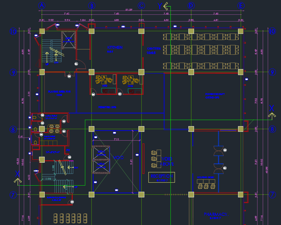
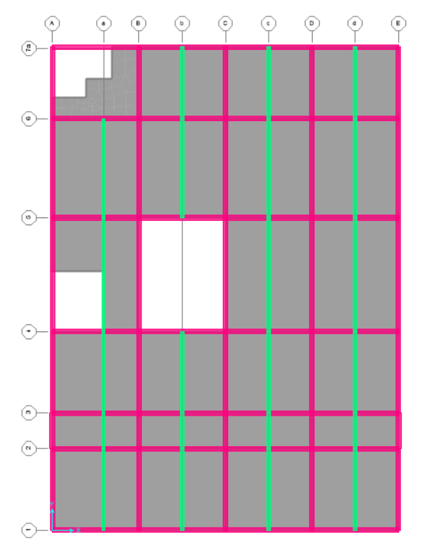
There is presence of secondary beam along y-axis dividing the slab in equal half [shown in fig of SAP analysis]
Pink = primary beam
Light green = secondary beam
For design of beam along y-axis, let’s take longest span beam (10.02m c/c).
The design of primary beam can be done under following steps:
- Preliminary design of beam
The detail about the preliminary design is discussed before. If you want to go there, then click here.
The preliminary design is based on the serviceability condition of deflection criteria. From IS 456:2000 clause 23.2.1,
L/d ≤ αβγδλ
Assume d = l/20.7 [ for continuous beam and Fe 500D ]
Where l is effective span which can be calculated from clause 22.2 of IS 456:2000.
So, d = 10.02/20.7 = 0.485 m
Assume diameter of bar = 20 mm and clear cover = 25 mm
As I have already discussed in preliminary design, we should increase the depth.
Adopt overall depth = 600 mm
So effective depth = overall depth – clear cover – half of diameter of bar
= 600 – 25 – 20/2 = 565 mm
And width = 400 mm
2. Load calculation
Partition load
Thickness of wall = 150 mm
Height of wall = floor to floor height – depth of beam
= 4.27 – 0.6 = 3.67m
Unit weight of partition material = 8 kN/m3 [ since AAC block as partition, if brick-wall then 19.2 kN/m3]
So, weight of partition wall = 8 * 3.67 * 0.15 = 4.4 KN/m
- Self-weight of beam
Size of beam = 250mm * 600 mm
Unit weight of concrete = 25 kN/m3
So, self-weight of beam = 25 * 0.4 * 0.6 = 6 kN/m
- Load from slab
Thickness of slab = 130 mm [From detailed design of slab, to learn more click here.]
Live load = 3 kN/m3
Floor finish = 1.5 kN/m3
So, weight of slab = unit weight * thikness of slab
= 25 * 0.13
= 3.25 kN/m2
Width of the slab loaded on beam = half the effective distance in left and half in right [since one way slab]
= 3.82/2 + 3.82/2
= 3.82 m
So, total load from slab = (live load + floor finish + slab weight) * loaded width
= (3 + 1.5 + 3.25) * 3.82
= 29.6 KN/m
Total factored load = 1.5 * (partition load + self-weight of beam + total load from slab)
= 1.5 * (4.4 + 6 + 29.6)
= 60 KN/m
3. Moment calculation
Since the beam does not meet the criteria for code. So we have either to use moment distribution method or structural design software. Here I use SAP2000, but you can also use other design analysis software.
In beam, we have to calculate reinforcement in support and mid span.
At support,
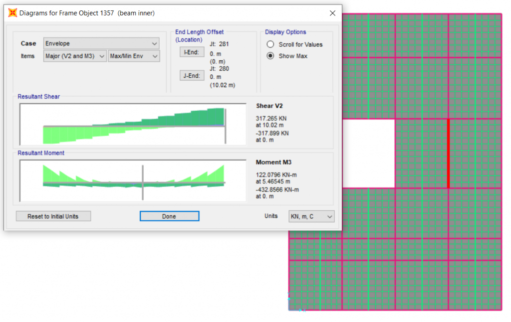
From SAP2000, [figure above]
Max. moment at support = – 432.86 KN-m
Shear force at support = 317.9 kN
At mid-span:
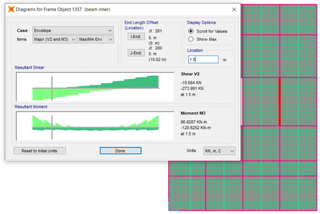
Since the curtailment or bent-up begin from 0.15* effective span, so for design of reinforcement in mid span we have to take maximum. For this case, the moment is maximum at cut-off point so, from fig. above
Moment for mid span = – 120.62kN-m and 122.08 KN-m Shear force at cutoff = 274 kN
4. Check for singly or doubly reinforced beam
For this, we have to calculate limiting moment
Mu,lim = 0.133 fck b d2 [ for fe 500]
= 0.133 * 30 * 400 * 5652 [fck = 30 N/mm2]
= 509.48 KN-m
So singly reinforced beam
5. Calculation of tensile and compression reinforcement.
For singly reinforced beam
At support,
Mu = 0.87 fy Ast [ d – fy Ast / fck b ]
432.86 * 106 = 0.87 * 500 * Ast [565 – 500 * Ast/ 30 * 400]
Ast = 2080.4 mm2
At mid-span, [ since the moment for top and bottom bar is nearly same so calculate for only one]
Mu = 0.87 fy Ast [ d – fy Ast / fck b ]
122.08 * 106 = 0.87 * 500 * Ast [565 – 500 * Ast/ 30 * 400]
Ast = 516.4 mm2
6. Calculation of number of bar provided and check for min. and max. limits
The assumed diameter of bar = 20 mm
Area of a bar = 3.14 * 202/4
= 314 mm2
At support,
Area of top [tensile] bar = 2080.4 /314 = 6.62 nos
At mid span,
Area of top [compression] bar = 516.4 / 314 = 1.65 nos
Area of bottom [tensile] bar = 516.4 / 314 = 1.65 nos
Checking limits:
- the maximum area of reinforcement provided = 4% of bD = 9600 mm2
- the minimum area of reinforcement required = 0.85 * bd/fy = 384.2 mm2
satisfying the limit so,
provide two bottom bar of diameter 20 mm throughout
provide two top bar of dimeter 20 mm throughout
for extra top bar a support = 7-2 = 5 nos
7. Arrangement of bar with spacing check
From code IS 456:2000 table 15, the clear distance between the bars should not be greater than 150 mm for Fe 500 with no moment redistribution.
Provide 3/3 number of 20mm bar on both top and bottom layer of beam at midspan.
Checking spacing = (width – 2 * clear cover – nos * diameter of bar ) / ( nos of bar -1)
= (400 – 2 * 50 – 3 * 20) / 2 = 120mm ok
Spacing of 7 bar in top support = (width – 2 * clear cover – nos * diameter of bar ) / ( nos of bar -1)
= (400 – 2 * 25 – 7 * 20 ) / ( 7-1 ) = 35 mm ok
8. Check for deflection
For deflection control criteria, using IS 456:2000 clause 23.2.1
For modification factor for tension reinforcement,
fs = 0.58 fy * area required / area provided
= 0.58 * 500 * 516.4/942.47
= 159
Percentage of steel = 3*314.16 *100 / 400*600 = 0.39 %
From fig.4, modification factor for tension reinforcement = approx. 1.85
From fig. 5, for compression reinforcement 0.9% , modification factor = 1.1
From fig. 6 modification value = 1
Allowable l/d ratio = basic value * modification value
= 26 *10/10.02 * 1.85 * 1.1 *1 = 52.8 > Assumed (20.7)
9. Check for shear
First calculate nominal shear stress Ⴀv = Vu / bd
= 318 * 1000 / 400 * 565
= 1.4 N/mm2
From table 19 of code IS 456:2000, calculate design shear stress Ⴀc
For steel percent 0.39% and M30 grade of concrete,
Ⴀc = 0.37 +(0.50-0.37)*(0.39-0.25)/(0.5-0.25)
= 0.44 N/mm2
and from table 20, the maximum shear stress Ⴀc,max = 3.5 N/mm2
If Ⴀv < Ⴀc < Ⴀc,max, shear reinforcement are to be designed.
10. Calculation of transverse reinforcement with spacing
The shear reinforcement can be calculated from the code IS 456:2000 of clause 40.4 (page 73).
Near the support, there is only stirrups to resist the shear force.
Shear resisted by reinforcement = Total shear minus shear resisted by concrete.
= (1.4 – 0.44) * 400 * 565
= 216.96 KN
Now,
Assume diameter of stirrups = 8 mm
Since two-legged stirrups so,
Area = 2 * 3.14 * 82/ 4
= 100.5 mm2
So,
Vus = 0.87 fy Asv d / sv
216960 = 0.87 * 500 * 100.5 * 565 / sv
Sv = 113.85 mm
At the point of bar bent-up
There are bent-up bars to resist shear stress beside the traverse reinforcement. The contribution of bent-up bar can’t be taken more than 50% of total shear resisted by reinforcement.
Since we have not provided any bent-up so all the shear is resisted by the vertical stirrups only. And the shear force decrease as we moves from support to mid-span so we can increase the spacing of stirrups.
Shear force at cut-off point = 274KN > 318 KN [at support]
The spacing of transverse reinforcement should not be greater than 300 mm or 0.75d .
0.75 d = 0.75 * 565 = 423.75
So provide stirrups of 8 mm diameter @ 100 mm c/c at support
And stirrups of 8 mm diameter @ 125 mm c/c at mid-span.
From the whole design procedure, it shows that the beam of size 400 mm * 600 mm gives satisfactory result. And also for economic design you can go for next trial with smaller dimension and check out all procedure.
ALSO SEE