

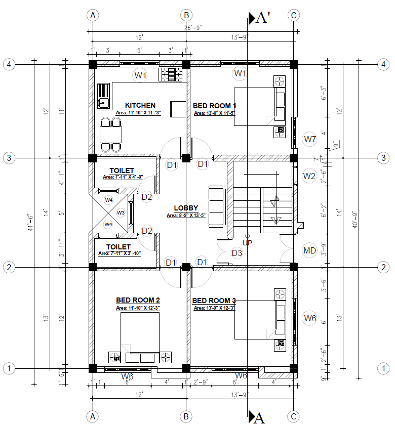
Design an isolated footing of the given building as shown:
Grade of concrete = 25 N/mm2;Grade of steel = 415 N/mm2
Column size = 1’ * 1’ = 305 mm * 305
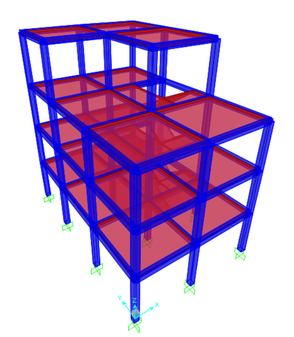
The structural design output value for isolated footing are:
| Footing | Output Case | Case Type | Step Type | F3 | M1 | M2 |
| Text | Text | Text | KN | KN-m | KN-m | |
| 1 | Envelope | Combination | Max | 303.316 | 43.4039 | 42.769 |
| 1 | Envelope | Combination | Min | 87.055 | -51.9247 | -33.9018 |
| 2 | Envelope | Combination | Max | 458.315 | 43.011 | 44.8181 |
| 2 | Envelope | Combination | Min | 172.074 | -51.2382 | -41.2312 |
| 3 | Envelope | Combination | Max | 315.226 | 39.4609 | 33.146 |
| 3 | Envelope | Combination | Min | 107.46 | -45.1896 | -42.3828 |
| 4 | Envelope | Combination | Max | 458.035 | 52.7445 | 51.6481 |
| 4 | Envelope | Combination | Min | 167.229 | -52.6878 | -40.9427 |
| 5 | Envelope | Combination | Max | 846.577 | 52.7589 | 60.9906 |
| 5 | Envelope | Combination | Min | 413.799 | -52.2924 | -51.5955 |
| 6 | Envelope | Combination | Max | 682.623 | 53.8126 | 43.9389 |
| 6 | Envelope | Combination | Min | 222.274 | -54.2414 | -56.0346 |
| 7 | Envelope | Combination | Max | 582.917 | 54.1581 | 59.9258 |
| 7 | Envelope | Combination | Min | 190.899 | -52.0849 | -47.9118 |
| 8 | Envelope | Combination | Max | 864.837 | 54.042 | 63.1715 |
| 8 | Envelope | Combination | Min | 414.096 | -51.179 | -57.7312 |
| 9 | Envelope | Combination | Max | 674.645 | 82.5598 | 45.1608 |
| 9 | Envelope | Combination | Min | 255.531 | -85.5023 | -60.7769 |
| 10 | Envelope | Combination | Max | 421.182 | 51.94 | 64.3109 |
| 10 | Envelope | Combination | Min | 122.955 | -43.831 | -52.0679 |
| 11 | Envelope | Combination | Max | 621.05 | 52.8944 | 69.562 |
| 11 | Envelope | Combination | Min | 234.156 | -42.7969 | -62.085 |
| 12 | Envelope | Combination | Max | 444.272 | 50.2985 | 53.506 |
| 12 | Envelope | Combination | Min | 142.649 | -38.8656 | -59.2972 |
For design example, take the critical one. The footing 8 is critical since it has highest axial force and high value of moment.
From column, factored axial load = 864.37 KN and Mx = 54.042 KN-m and My = 63.1715 KN-m
Step 1: Calculate factored loads and bending moment
The factored axial load and factored bending moment from the column is obtained from the structural software. Add 10% for self-weight of footing and soil above the footing.
Factored axial load on footing = factored axial load from column + self-weight of footing
= 1.1 * 864.37
= 950.8 KN
The eccentricity is calculated as,
Eccentricity on x-axis = Mx/P = 54.042/864.37 = 0.0625 m = 62.5mm
Eccentricity on y-axis = My/P = 63.17 / 864.37 = 0.073 = 73 mm
For simplicity in construction and supervision, it is better to increase the thickness of footing rather than shifting but it makes the structure little bit uneconomical. It is compulsory to go for non-shifting case if there is possibility of moment reversal.
Here we discuss about the only non-shifting case of isolated footing.
Step 2: Calculate an area of footings based on the factored axial load
Area of footing = service load / safe bearing capacity of soil
Service load = factored load / factor of safety = 950.8 / 1.5 = 633.87 KN
Safe bearing capacity of soil = 150 kN/m2
so, area of footing = 633.87 / 150 = 4.226 m2
Adopt square footing
L =B = √4.226 = 2.055m = 2055 mm
Take size of isolated footing = 2200 mm * 2200 mm
Step 3: Calculate critical bending moment:
The critical section for the bending moment is taken at the edge the column in case of column footing.
In Non-Shifting case, the ultimate soil pressure varies uniformly over the area of footing.
Ultimate soil pressure Pu = design load / area of footing * (1± 6e/(B or L))
= 950.8 / 2.22 *( 1 ± 6 * 73/ 2200)
= 235.56 KN/m2; 157.36 KN/m2
For one edge, + sign is used and for other side – sign is used depending upon position of eccentricity. But for design it okey to take any one side of the footing because there may be case of moment reversal in the building.
Find the maximum soil pressure Pu,max and soil pressure at the edge of column Pux or y, then the moment should be calculated on both axis.
Pu,max = 235.56 KN/m2
Puy = 235.56 – (235.56 – 157.36)/ 2.2 * (2.2-0.305)/2
= 201.88 KN/m2
Puy,avg = ½ * (Pu,max + Puy)
= (235.56 + 201.88)/2 = 218.72 KN/m2
For moment calculation, first take average of Pu,max and Pux or y then
Muy = ½ Puy,avg *B ( 0.5 L – 0.5l)2
= ½ * 218.72 * 2.2 (0.5 * 2.2 – 0.5 * 0.305)2
= 216 KN-m
Mu is max. of Mux and Muy
L and B is for footing and l and b for column
Step 4. Thickness of Footing
The thickness of footing is calculated from the maximum critical bending moment.
Dreq. = √ (Mu / 0.138 fck B)
= √ (216 * 106 / 0.138 * 25 * 2200)
= 168.7 mm
Increase depth for 1.75 to 2 times more than calculated value for shear considerations [This is done just to decrease the possibility of shear failure of footing while checking]
i.e. d = (1.75-2) Dreq
= 2*168.7 = 337.4 mm
Adopt thickness of footing equal to 340 mm.
The value of d is the effective thickness of footing. For overall thickness, clear cover and half of diameter of reinforcement should be added.
Step 5: Calculation of reinforcement
The reinforcement is calculated from the critical maximum moment obtained in the step 4
Mu = 0.87 fy Ast [ d – fy* Ast / fck*b]
216 * 106 = 0.87 * 415 * Ast [ 340 – 415 * Ast / 25 * 2200]
Ast = 1834.24 mm2
Provide 12 mm diameter of bar.
Area of a bar Ast1 = pi * 122/4 = 113.1 mm2
Spacing of bar S = Ast1 * B /Ast = 135.65 mm
Provide spacing of 130 mm
Area provided = Ast1*B / S = 113.1 * 2200/130 = 1914 mm2
Percentage of reinforcement provided = Ast / Bd * 100 = 1914 * 100 / 2200*340
= 0.255 %
The area of reinforcement is greater than 0.12% of Bd., OK
Step 6. Check for one way shear
The critical section is taken at a distance d away from the face of column.
Pu,max = 235.56 KN/m2
At critical section, ie at d distance from edge of column
Puy = 235.56 – (235.56 – 157.36)/ 2.2 * (2.2-0.305- 2*340)/2
= 213.96 KN/m2
Puy,avg = ½ * (Pu,max + Puy)
= (235.56 + 213.96)/2 = 224.76 KN/m2
Shear force per meter, Vu = Pu,avg * B *{0.5(L-l) – d}
= 224.76 * 2.2 * [0.5 (2.2 – 0.305) – 0.34]
= 300.4 KN
Since the footing is square so the shear stress is same for both axis.
Nominal shear stress Ʈu = Vu /Bd
= 300.4 / 2.2 * 0.34
= 401.6 KN/m2
= 0.4 N/mm2
The nominal shear stress should be less than shear strength of the footing, that is
Shear strength Ʈuc = k Ʈc
The value of k depend up on the thickness of footing which can be obtained from clause 40.2.1.1 of IS code 456:2000
K = 1 [For depth more than 300 mm]
And the value of Ʈu depend upon the grade of concrete and area of reinforcement which can be obtained from Table19 of IS code 456:2000
For M25 grade of concrete and percentage of steel = 0.25%
Ʈu = 0.36 N/mm2
Since, Ʈuc < Ʈv , so unsafe
Increase the depth of footing. Adopt 375 mm
Trial 2:
Shear force per meter, Vu = Pu,avg * B *{0.5(L-l) – d}
= 224.76 * 2.2 * [0.5 (2.2 – 0.305) – 0.375]
= 283.08 KN
Since the footing is square so the shear stress is same for both axis.
Nominal shear stress Ʈu = Vu /Bd
= 283.08 / 2.2 * 0.375
= 343 KN/m2
= 0.343 N/mm2
The nominal shear stress should be less than shear strength of the footing, that is
Shear strength Ʈuc = k Ʈc
K = 1 [For depth more than 300 mm]
For M25 and percentage of steel = 0.25%
Ʈu = 0.343 N/mm2
Since, Ʈuc > Ʈv , so safe
Step 7: Check for two way action of shear – punching shear
The critical section for two-way shear is taken at a distance d/2 away from the face of column.
Pu,max = 235.56 KN/m2
At critical section, ie at d/2 distance from edge of column
Puy = 235.56 – (235.56 – 157.36)/ 2.2 * (2.2-0.305- 0.375)/2
= 208.54 KN/m2
Puy,avg = ½ * (Pu,max + Puy)
= (235.56 + 208.54)/2 = 222.05 KN/m2
Shear force per meter, Vu = Pu,avg [ L*B – (l+d)*(b+d)]
= 222.05 * [2.2 * 2.2 – (0.305+0.375)* (0.305+0.375)]
= 972.04 KN
Nominal shear stress Ʈu = Vu /bo d
Where b0 = perimeter of critical section = 2(l+b+2d) = 2* (0.305 +0.305 + 2 * 0.375) = 2.72 m
Ʈu = Vu /bo d
= 972.04 / 2.72* 0.375
= 952.98 KN/m2 =0.95 N/mm2
The nominal shear stress should be less than shear strength, that is
Ʈuc = 0.25 √fck = 0.25 * √ 25 = 1.25 N/mm2
Hence, safe in punching shear.
Step 8: Check for development length
The development length can be calculated using the clause 26.2.1 of IS code 456:2000,
Development length Ld = Փ * 0.87 fy / 4τbd
Where, Փ = 20 mm = diameter of longitudinal bar of column
τbd = 1.4*1.6 = 2.25 = design bond stress given in clause 26.2.1.1.
Required development length Ld = Փ * 0.87 fy / 4τbd
= 20 * 0.87* 415 / 4*2.25 = 802.33 mm
The calculated development length should be less than the available development length in the shorter side.
Available development length = L/2 – l/2 – side clear cover.
= 2200/2 – 305/2 – 65
= 882.5 mm > Req. Ld , no anchorage required.
The value of side clear cover is normally taken as 50-75 mm
Step 10: Design Summary with arrangement of reinforcement.
The design summary isolated footing is as,
Size of footing = 2200 mm * 2200 mm
Effective depth of isolated footing = 375 mm
Reinforcement along both sides = 12 mm diameter bar @ 130 mm c/c
Overall depth of spread footing = effective depth + effective cover
= 375 + 65 = 440 mm
ALSO READ