

Design of basement wall
Basement walls are exterior walls of underground structures or retaining walls which resist lateral earth pressure as well as additional pressure due to other type of loading. It carries lateral earth pressure generally as vertical slabs supported by floor framing at the basement level and upper floor level. The axial forces within the floor structures are either resisted by shear walls or balanced by the lateral earth pressure coming from the other side of the building. Although basement walls act as vertical slabs supported by the horizontal floor framing, it should be noted that during the early construction stage when the upper floor has not yet been built, the design of basement wall may have to be as a cantilever.
The basement wall is designed as the cantilever slab with the fixity provided by the raft foundation. Let’s understand the design of basement with an example.
Example: Design a basement wall of a building having basement height 3.2 m. The unit weight and angle of internal friction of soil present in that area is foud to be 18KN/m3 and 300 respectively. The surcharge produced due to vehicular movement is given by 10 KN/m2. Provided grade of concrete = M30 and grade of steel = 500D
The design of basement wall involves the following steps:
Design Constants
Clear height between the floor (h) = 3.20 m
Unit weight of soil, γ = 18 KN/m3
Angle of internal friction of the soil, Ѳ = 300
Surcharge produced due to vehicular movement Ws = 10 KN/m2
Moment calculation
Lateral load due to soil pressure,
Pa = ½ * Ka x γ x h2
Where,
Ka = coefficient of active lateral pressure
= (1-sinѲ)/(1+sinѲ)
Given, Ѳ = 300
Ka = (1-sin30)/(1+sin30)
= 1/3
So,
Pa = ½ * Ka x γ x h2
= ½ * 1/3 * 18 * 3.22
= 30.72 KN/m width of wall
Lateral Load due to surcharge load,
Ps = Ka x Ws x h
= 0.333x10x3.2
= 10.67 KN/m width of wall
Since the design of basement wall is as cantilever, so bending moment is maximum at the base of wall.
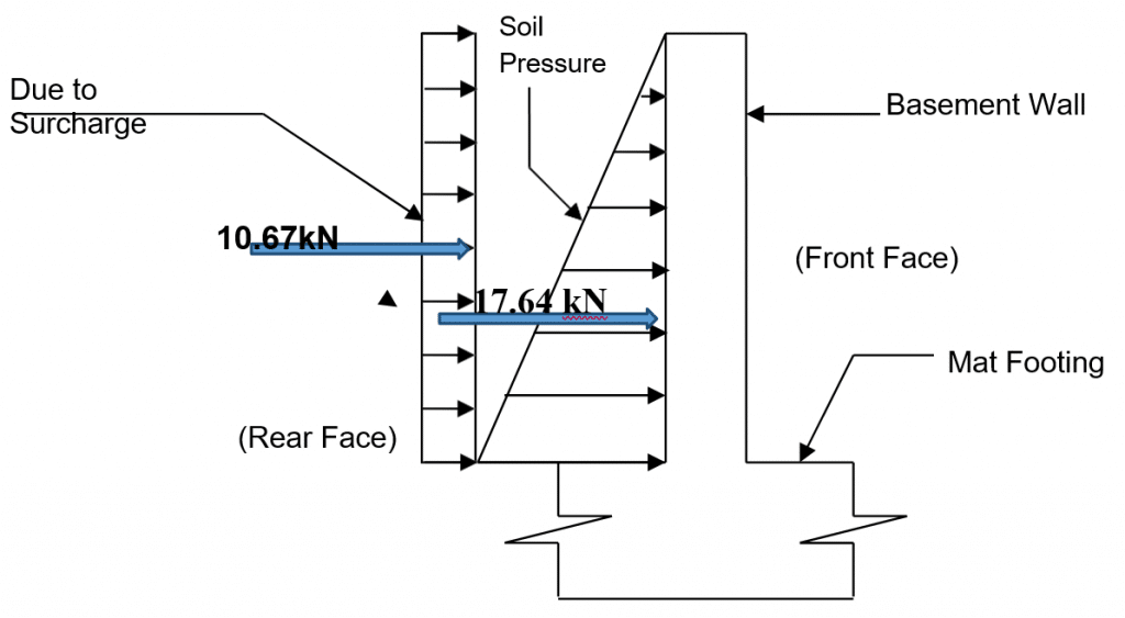
Bending moment at the base of wall can be calculated as
Mx = Pa * h/3 + Ps * h/2
[Since, soil pressure is uniformly distributed and surcharge load is uniformly variable as shown in figure]
Mx = 30.72 * 3.2/3 + 10.67 * 3.2/2
=49.84 KNm
Factored moment (Mu) = 1.5 * 49.84 = 74.76 KNm
Calculation of thickness of basement wall
Assume unit width of wall
Effective thickness of basement wall (d)
Mu = 0.36 fck b xu/d [d – 0.42 xu]
where,
fck = characteristics strength of concrete
xu = distance from neutral axis
For Fe500, xu/d = 0.46
Mu = 0.1336 fck b d2
74.76 * 106 = 0.1336 * 30 * 1000 * d2
d = 136.57 mm
Provide D = 200 mm with clear cover 30mm and 12mm dia. bars.
So, d = 200-30-12/2=164mm
Design of reinforcement:
- Main/Vertical reinforcement
The vertical reinforcement of the basement wall is calculated from the factored bending moment and is given by,
Mu = 0.87 fy Ast [ d – fy Ast / fck b]
Assuming unit width of wall,
74.76 * 106 = 0.87 * 500 *Ast [164 – 500 *Ast / 30 * 1000]
On solving we get,
Ast =1192.44 mm2
Check for minimum reinforcement and max. diameter
The minimum reinforcement provided is given by,
Ast,min = 0.12% of bD [ IS 456:2000 clause 32.5 (a)]
= 0.0012*1000*200 = 240mm2 < 1192.44 mm2
Maximum diameter of bar = D/8 [ IS 456:2000 clause 26.5.2.2]
= 200/8 = 25mm > 12mm
Area of a bar,
Ab = π*122/4=113 mm2
Spacing of bar = 1000*113/1192.44 = 94.76 mm < 3D or 450mm (600 or 450mm)
Provide 12mm dia. bars @ 90mm c/c at earth face.
Provided Ast = 1000*113/90 = 1255.56 mm2
Since thickness of wall is taken as 200 mm, horizontal and vertical reinforcement are necessary on each face of the wall.
Provide 12mm dia. bars @ 300mm c/c at inner face.
Calculation of distribution/horizontal reinforcement
In the design of basement wall, the minimum distribution reinforcementshould be provided as mentioned in code IS 456:2000 clause 32.5 (c).
Minimum reinforcement required = 0.002*D*h
=0.002*200*3200
=1280 mm2
As the temperature change occurs at earth face of basement wall, 2/3 of horizontal reinforcement is provided at earth face and 1/3 of horizontal reinforcement is provided at inner face.
Horizontal Reinforcement steel at inner face,
=1/3*1280 = 426.67 mm2
Spacing of 12mm dia bar = 1000*113/426.67 =264.84 mm
Provide 12 mm dia bar @ 250mm c/c
Horizontal Reinforcement steel at earth face,
= 2/3*1280 = 832mm2
Spacing of 12 mm dia bar = 1000*113/823=132.42mm
Provide 12mm dia bar @ 120mm c/c
Check for shear
Assuming the section will be critical the bottom of wall.
Shear force at that section is
Vu = Ka*Ws*h+1/2 * Ka *ɣ * h2
[ All the parameters are already mentioned]
Factored shear force,
Vu =1.5 (0.333*10*3.2 + ½ * 0.333*18*3.22)
= 62.08 KN
Nominal shear stress, τu = 62.08*103/(1000*164)
= 0.3785 N/mm2
For Pt=100*1192.44 /(1000*164)=0.727% and M30 concrete,
Permissible shear stress,
τu = 0.5 + (0.59-0.5)/(0.75-0.5) * (0.727-0.5)
= 0.58N/mm2 > 0. 3785 N/mm2 Ok
Check for deflection
Effective height he = clear height of basement wall + half effective thickness of wall [IS 456:2000 clause 22.2 (c)
= 3.2+0.164/2 = 3.282 m
Allowable deflection = height of basement wall / 250 [IS 456:2000 clause 23.2 (a)]
=3.282/250 =13.13 mm
Actual deflection= 𝑃𝑠 * he4/8𝐸𝐼+𝑃a * he4/30𝐸𝐼
Where, E = modulus of elasticity = 5000√fck
I = moment of inertia = b* D3/ 12
So, E = 5000√30= 27386.12 N/mm2
I = 1000 * 2003 / 12 = 6.67 * 108 mm4
Actual deflection= 𝑃𝑠 * he4/8𝐸𝐼+𝑃a * he4/30𝐸𝐼
= he4/𝐸𝐼 [ Ps / 8 + Pa /30]
= 32824 / 27386.12*6.67*108 [ 10/8 + 18*3.282/30] * 1/3
= 5.21mm
Ok
Calculation of development length:
The development length is calculated as mentioned in IS code 456:2000 clause 26.2.1
Development length, Ld = 0.87𝑓𝑦𝜙/4𝜏𝑏𝑑
= (0.87*500* Ф)/(4*1.6*1.5)
= 45.3 Ф = 45.3*12 = 543.75 mm
Curtailment of vertical reinforcement
No bars can be curtailed in less than Ld distance from the bottom of stem.
Taking one third height from base (2.13 m from top) for the curtailment.
Calculation of moment at curtailment point:
Lateral load due to soil pressure, Pa = Ka x γ x h2/2
= 0.333x18x2.132/2
= 13.6 KN/m
Lateral Load due to surcharge load,
Ps = Ka x Ws x h
= 0.333x10x2.13
= 7.1 KN/m
Characteristic Bending moment at the point of curtailment:
Mx= 13.6 * 2.13 /3+7.1 *2.13/2
= 17.2 KNm
Factored moment = 17.2*1.5= 25.826 KNm
Bending moment, M = 0.87fyAst(d-fyAst/𝑓𝑐𝑘𝑏)
So, 25.826*106 = 0.87*500* Ast (164-500 Ast/30*1000)
On solving we get,
Ast=376.4 mm2 > Ast,min = 240mm2
Spacing of bar = 1000*113/376.4 = 300.21mm < 3D or 450mm (450 or 450mm)
Provide 12mm dia. Bars @ 270mm c/c at earth face above the point of curtailment.
Also read